(Deprecated) Memory Wiping - A First Test
Wiping cluster memory and proving that it's been wiped. Initial experiments with H200s.
Contents
A regular memory wipe bounds what type of computations can be done. Combined with network taps, recomputation and side-channel protections, memory wipes can build confidence that no undeclared training is happening within a cluster.
Background
A cluster is operated by the prover and checked by the verifier. The prover’s goal in a memory wipe is to provide proof to the verifier that they have wiped their memory. We want to achieve that without the verifier needing to trust the prover’s hardware; we’d also like this operation to take ~minutes rather than hours or days.
Our approach is for the verifier to give the prover a set of random numbers to write to memory. The only way the prover can read them back to the verifier is if they filled their entire memory with those numbers, meaning nothing else can be stored there. This is a Proof of Secure Erasure (PoSE).
Simple in theory
A few of the system challenges when experimenting with memory wipes on a tray of H200s
Devices abstract memory for the user
The main challenge with implementing this is that modern devices don’t normally let you write directly to memory; that is the domain of the OS and the CPU’s memory management unit (MMU). The OS and the MMU work together to manage the RAM such that when an application starts it believes it has access to all available memory as defined by the OS. This is often larger than the actual available memory; this is achieved using virtual memory and memory maps.
Both physical memory and virtual memory is split into chunks known as pages, these pages are then managed by the MMU using a memory map, the memory map acts as a lookup table between the virtual and the physical memory.
When the user allocates some memory it is first assigned an address in the virtual memory space inside a page and the OS passes the request onto the MMU which then assigns it to an available space in a physical page and location.
If a new page is required to be created but the RAM is currently full the MMU returns a fault to the OS and the OS will request the MMU to evict a page provided by the OS to free the memory. Later if the user asks for data that is not currently in the RAM but is now on disk the same process applies, with the OS nominating one or more pages to be evicted and the user’s page is then brought in.
/dev/mem
The main way to work around this limitation is to use memory mapping (mmap()) on a special device in linux called “/dev/mem” which represents the raw physical memory, unfortunately most standard builds of Linux have this disabled, but it can be enabled when building the OS from scratch. This allows us to access physical memory but we still find our process being halted, having our memory paged or even linux terminating our process if it decides it needs its memory back.
The correct way to solve this is at the OS level (“ring 0”). The program should be executed as a kernel, which will give it privileged access to the system to allow us to disable paging to disk for our memory. This does mean the OS requires more memory, but if we have consumed it all, the OS will simply crash.
Wiping everything
How do we maximise the amount of memory we wipe? Ideally, we would wipe every tiny bit of memory, disk, hbm etc., but this isn’t trivial.
We should not overwrite drivers and OS, which means there will always be some memory that we’ve not overwritten. To minimise the amount of memory we don’t wipe we start with a stripped-back OS with as little overhead as possible. We only include the components we need to perform the wiping. Once memory wiping is complete, we can reinstall/initialise a full OS.
Wiping it all at once
The last challenge is one of a constraint to the system, simply that all data must be simultaneously wiped across the system. If we were to wipe one disk, then the next, an attacker could simply move the data between the disks. The same goes for the compute trays, where it may not be possible to observe the inter-tray communications; data could simply be moved between devices. On a single device, this problem is easier to solve as we simply have to label all memory and disk space before we perform the challenges and randomly challenge data from memory and disk such that an attacker cannot guess where we will request data from next.
There are lots of bits of memory
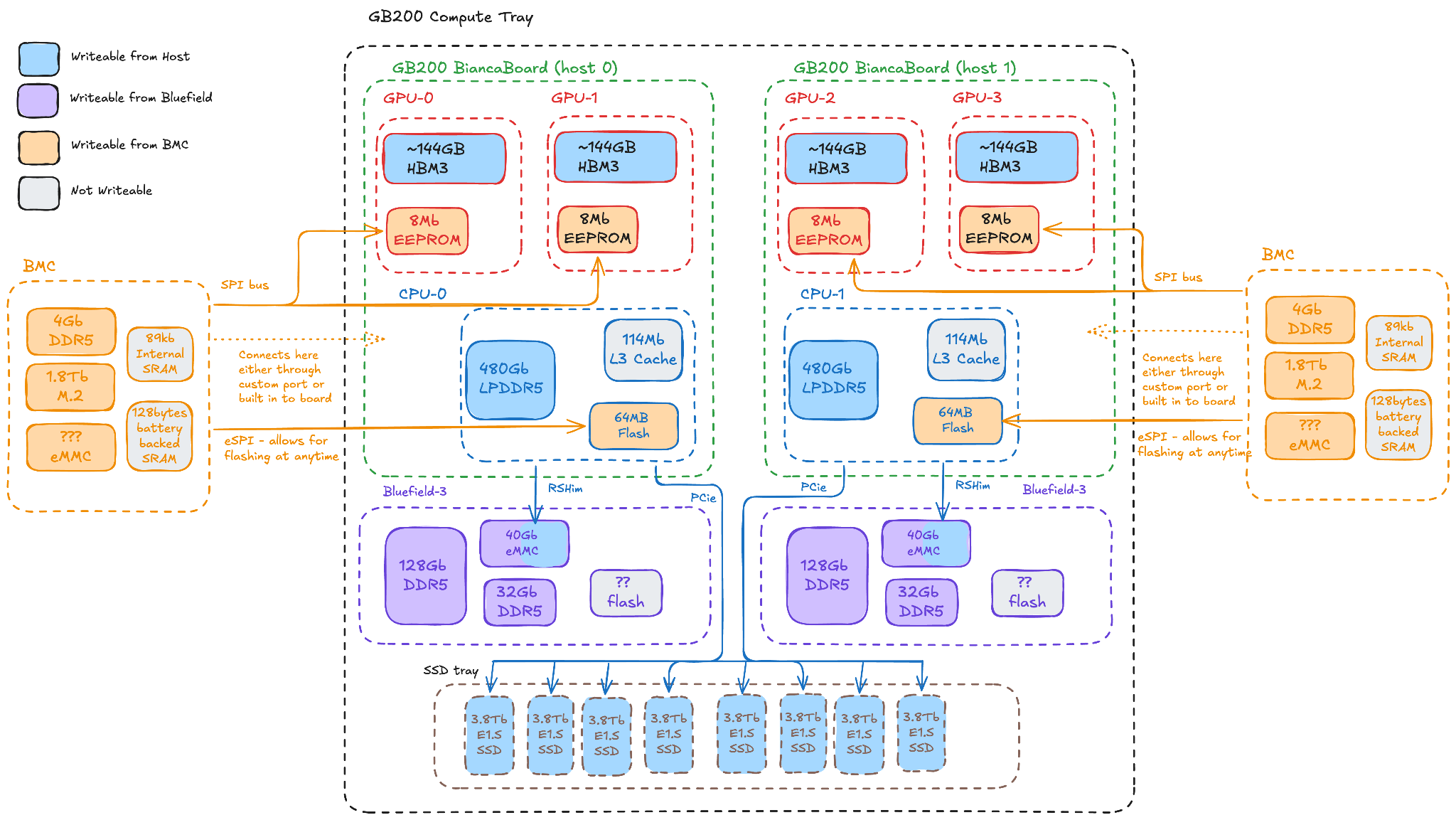
These are estimates of where all of the memory is on a GB200 system, and how much is non-wipeable (e.g. due to drivers and keys).
| Device | Store | Memory per device | Rack total | Non-wipeable memory |
|---|---|---|---|---|
| GPU | HBM3 | 192 GB | ≈ 13.8 TB | <100MB (drivers) |
| firmware EEPROM | 8 MB | ≈ 576 MB | <1MB (keys) | |
| Host | DRAM (LPDDR5X) | 480 GB | ≈ 17 TB | <50GB (usable capacity) |
| BIOS flash | 64 MB | ≈ 2.3 GB | <1MB (keys) | |
| M.2 SSD | 1.8 TB | ≈ 32 TB | <400GB (usable capacity) | |
| L3 cache | 114 MB | ≈ 4 GB | 114MB (cache) | |
| BMC | DRAM (DDR) | 4 GB | ≈ 72 GB | <128MB (OS) |
| internal SRAM | 89 KB | ≈ 1.6 MB | 89 KB (next boot) | |
| battery-backed SRAM | 128 B | ≈ 2.3 KB | 128 B (next boot) | |
| DPU | DRAM (DDR5) | 32 GB | ≈ 1.1 TB | <128MB (OS) |
| on-board SSD | 128 GB | ≈ 4.6 TB | <60GB (usable capacity) | |
| eMMC (boot + OS) | 40 GB | ≈ 1.4 TB | <8G (usable capacity) | |
| Tray | E1.S NVMe SSD | 3.84 TB | ≈ 553 TB | <700GB (usable capacity) |
| Various | One-time-programmable | — | — | <10MB (keys) |
Proof of Secure Erasure
The PoSE protocol relies on storing known data on the Prover and then having the verifier challenge that data at random to ensure that the prover has stored the data. There are 2 ways proposed to do this: you either stream to the device enough random data to fill all available memory, or propose an algorithm for calculating the data on the device from a random key.
| Fill | The prover writes data to every location to be erased. |
| Challenge | The verifier requests the contents of randomly chosen locations under a timeout and checks them against the expected values. |
Pros and cons of streaming versus generating the data on device:
- Streaming. Network bandwidth becomes the bottleneck. Regular links operate at a 400 Gb/s interface. That means it would take 2-3 hours to move the 500TB required at rack scale.
- On device. This removes the network link from the critical path, at the cost of doing more computations on the device being erased.
We chose to generate the fill on the device using the approach described in (arXiv:2401.06626). Two things that we want to ensure:
- The prover is able to quickly generate the data for the challenges while being challenged.
- The verifier shouldn’t have to store all the information the prover is storing.
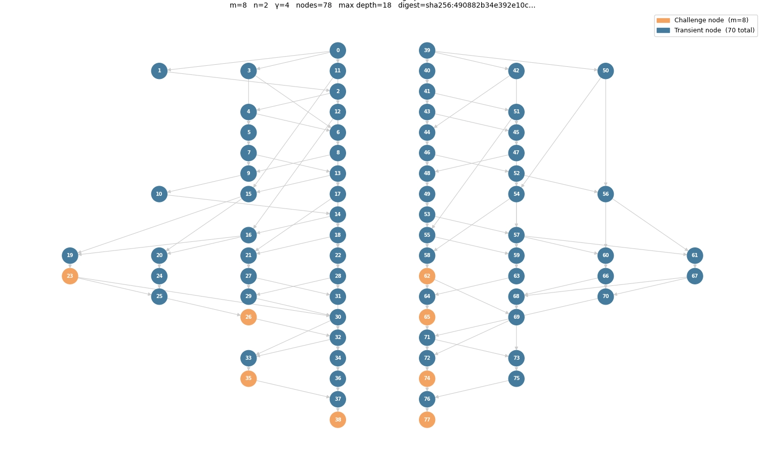
We achieve this by constructing a directed acyclic graph (DAG) — a set of nodes joined by one-way edges with no cycles. One node maps to each memory location to be filled. Each node n is given a label L(n), the value to be written to its location:
where H is a hash function, p₁…p_k are the nodes with edges into n (its parents), ∥ is concatenation, and a root node with no parents takes L(n) = H(n). A node’s label depends on its parents’ labels, so no label can be produced without first producing everything upstream of it.
The verifier sends the seed, pre-computes the labels it intends to challenge, and so knows the correct answer for any location without holding the whole fill.
We can make this more efficient by implementing a special case of a DAG: each node has a fixed two parents. This buys three properties:
- The label is computed layer by layer and written in place — each label overwrites the original data in its location, and computing a layer only reads labels already written — so the construction needs no memory beyond what it is erasing.
- Two parents per node keep each hash small and the fill close to one hash per location.
- Deleting a block of nodes does not isolate a small, cheaply recomputable subgraph — many independent paths run through any deleted region — so an attacker cannot free a region and reconstruct only the challenged labels within the timeout.
How the PoSE resists shortcuts
The fill does not need a cryptographically strong hash; the graph structure and timed challenges relax that. The one requirement is that H behaves as a random oracle: knowing one output gives no way to produce another without performing the hash.
Experiments
Raspberry Pi - demonstrating the algorithm
To test the setup we run the basic algorithm on a Raspberry Pi 5, erasing its RAM and a connected SSD.
The first stage was our own custom image, stripped as far back as possible — as much disabled at build time as we could manage, down to the display drivers.
With no display, we attached a UART for a live debug stream without any extra OS overhead. And rather than write the image to an SD card, we network-booted it, which gave two bonuses: the OS and its overhead lived in one place instead of being managed separately, and a rebuild-and-reboot redelivered the image automatically.
The erasure daemon itself is written in C and built into the kernel, sharing its graph and hash libraries with the Rust verifier so both compute the same graph and labels. The most complex part was managing which memory could and could not be erased: get it wrong and the result was the OS’s out-of-memory killer killing the process, a segmentation fault, or a complete crash from trampling the OS’s own memory.
Once a simple single-threaded version was wiping >1,900 MB of the 2 GB of RAM and all of the attached NVMe — albeit slowly — we set about optimising it through in-place labelling, multi-threading, and SIMD. The Pi’s Broadcom VideoCore is not CUDA-capable, so there is no GPU path here. However the GPU and CPU share memory which we wipe regardless.
H200 Implementation
After testing the setup on a Raspberry Pi we tested on our H200s.
Hash selection
The hash must behave as a random oracle and run fast enough to fill memory in a usable time. We benchmarked four candidates on the target hardware (CPU: AMD EPYC 9335, 32-core; GPU: NVIDIA H200 NVL), each producing labels from small inputs (56–192 bytes), over one million hashes:
| Algorithm | Device | Hash rate | Throughput | Label |
|---|---|---|---|---|
| BLAKE3 | EPYC 9335 (CPU) | 7.95 × 10⁶ h/s | 1,456 MB/s | 32 B |
| BLAKE3 | H200 NVL (GPU) | ~1.23 × 10⁷ h/s | 2,252 MB/s | 32 B |
| DUAL-AES-PRF (AES-128-CBC-MAC, AES-NI) | EPYC 9335 (CPU) | 40.9 × 10⁶ h/s | 4,373 MB/s | 32 B |
| SipHash-2-4-128 | EPYC 9335 (CPU) | 51.7 × 10⁶ h/s | 2,760 MB/s | 16 B |
The result splits by hardware:
- On the CPU, Dual-AES-PRF and SipHash beat BLAKE3. The inputs are small — BLAKE3’s weakest case — and AES-NI and SipHash are cheap on short messages. (Dual-AES-PRF is a pseudo-random function built from AES-128-CBC-MAC: not a hash, but it meets the random-oracle requirement.)
- On the GPU there is no hardware AES, so BLAKE3 leads.
- SipHash is fastest per hash but has a 16-byte label, which doubles the label count N for a given store, so its fill time does not beat Dual-AES-PRF’s.
We therefore use BLAKE3 on the GPU (for HBM) and Dual-AES-PRF on the CPU (for DRAM). We keep a BLAKE3 CPU path for the verifier, which may have no GPU.
Fill time
The fill writes one label per location and computes one hash per label, so its completion time is set by the hash rate. Let M be the size of a store in bytes, b the label size in bytes, and r the hash rate in hashes per second. The number of labels is N = M / b, and the fill time is
Capacities here use GiB = 2³⁰ bytes. The hash rates are measured (below); the capacities are datasheet figures. As a worked example, for one host’s DRAM (M = 490 GiB, b = 32 bytes) at the measured Dual-AES-PRF rate (r = 40.9 × 10⁶ h/s):
For one GPU’s HBM (M = 190 GiB, b = 32 bytes) at the measured BLAKE3-on-GPU rate (r = 12.3 × 10⁶ h/s):
The binding constraint differs by store:
- DRAM and HBM are hash-bound. The store’s own write bandwidth (hundreds of GB/s) far exceeds the rate at which labels are produced, so the hash sets the time.
- SSDs are bandwidth-bound. A label rate of 40.9 × 10⁶ h/s at 32 bytes is ~1.3 GB/s from one CPU thread — comparable to an SSD’s write speed.
The per-host aggregate with a single-threaded workload is below. This is a first-pass estimate assuming 25% overhead for graph construction, allocation, and other work.
| Store | Assumed volume | Estimated time |
|---|---|---|
| Disk | 15.36 TB (4 × 3.84 TB) | 17,457 s ≈ 4 h 48 m |
| HBM | 280 GB | 1,382 s ≈ 23 m |
| DRAM | 490 GB | 535 s ≈ 8.9 m |
| Total (sequential) | — | 19,374 s ≈ 5 h 22 m |
GPU and disk work use different resources, so they overlap; the GPU time is absorbed into the disk time, giving ~4 h 57 m for one host. Storage dominates.
The same construction applies to the BMC and DPU, which run Linux on smaller stores and should finish faster (unconfirmed without representative hardware). At rack scale, each device runs as a separate session and the sessions start together, so the wall-clock approaches that of the slowest single device — set by its storage — not the sum across devices. The worst case, with sessions forced to run synchronously, is expected below 18 hours.
Challenge time
During the challenge phase, the prover reads labels from random locations and returns them before a timeout. Almost every read is a cache miss — slow per access, but that is the intended behaviour. The access pattern must be unpredictable so the prover cannot pre-stage answers. Even so, we estimate sampling 0.1% of all labels on a GB200-scale system at ~8 minutes. The timeout per challenge is set small enough that the prover cannot recompute the label on the fly and large enough for a genuine lookup and network round-trip to the verifier.
What’s next?
- Dealing with usable capacity vs physical capacity on SSDs (and RAM). If we don’t trust the hardware, we can’t trust that the buffer capacity isn’t used to store data covertly. This is managed by a small micro-controller on the SSD. Can we reprogram that?
- Writing to the cache. Typically in an OS a cache is not directly addressable. However, during the early boot phase of many devices the CPU is unable to access the DRAM. As a result part of the cache is assigned as “Cache-as-ram” to allow it to begin the boot process. This mode is only available to L2 & L3 and is not supported by newer CPUs (with other techniques used instead). This does however suggest it may be possible to run the OS directly from the system cache or extend the addressable memory with the cache on certain devices.
- Erasing real memory and storage addresses. Demonstrate a kernel that writes to specific physical RAM addresses while Linux runs, then to specific SSD addresses, then fold both into a minimal network-booted image that mounts the GPUs and disks and does not page. This is the integration task that allows us to run NVIDIA drivers. That in turn allows us to write to HBM on e.g. a B200.
- Erasing the GPU HBM. Demonstrate the wiping of the GPU’s on a device. Here we need to integrate the NVIDIA drivers into our image, this will allow us to wipe not just the RAM and disks but the GPU as well on devices such as a B200’s.
- The last few percent. Reaching storage devices’ firmware-reserved regions, caches, host BIOS flash and GPU EEPROM via the BMC, and BMC eMMC, and establishing what can and cannot be proven erased. SSDs reserve part of their flash for internal firmware; whether that region can be expanded to hide data, and how it is secured, is open research — vendor tools can update it, so the region is reachable, but the difficulty of misusing it is unknown.
- The NVLink switches. The NVLink/NVSwitch trays run a locked-down custom operating system (NVOS) provisioned through the Open Network Install Environment, on an x86 COM-Express controller. Whether a custom wipe image can be loaded (gated by secure boot) and what memory and storage they contain is undocumented and needs investigation.
- Simultaneous wipe of Host, DPU and BMC. Can we cleanly wipe a whole tray simultaneously so that no data can be hidden on a device in the tray? The main challenge here will likely be deployment, typically the Host OS and the DPU’s OS is deployed via the BMC meaning we need to deploy these images before we modify the BMC itself.