What is Power Supply Ripple Rejection?
Analogue electronic design often requires low-noise performance. One important parameter is the Power Supply Rejection Ratio (PSRR) of a circuit. This is the circuit’s ability to reject noise from your power supply, an especially important performance characteristic when you don’t know the quality of the supply the board will end up connected to.
The PSRR is defined as the ratio of a measured deviation on the output as you force a deviation on the power supply itself, usually given in dB.
Measuring this sounds easy, you just need to superimpose a sine wave of a given amplitude and frequency on top of your power supply and measure the output of your circuit — but in reality, that superimposition is harder than you think. The crux of it is this: to measure PSRR effectively, you need an incredibly clean supply with a very well-controlled wave added over the top. Both of these things are simple enough on their own, but how do you go about the addition?
Expensive power supplies have fancy features that make this possible, but cheap solutions are much harder to come by. COTS injection transformers offer an alternative to a fancy power supply, but they are either expensive or have very low bandwidth.
Whilst developing a new brain recording device, we needed to measure the PSSR of our design, so we chose to spin our own solution.
Amodo Power Supply Ripple Injector
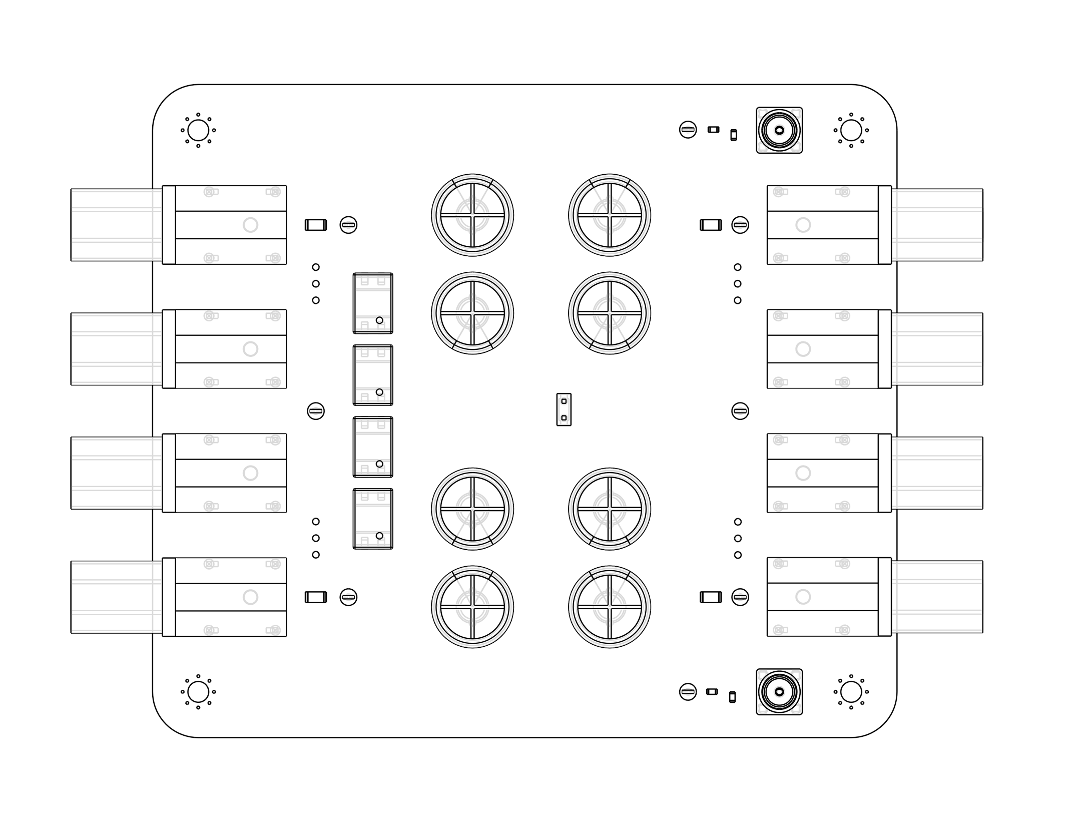
 PSRR PCB
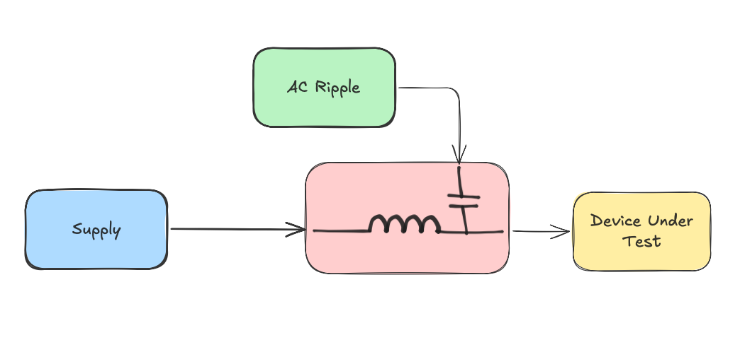
The core principle is simple: Clean lab power supply + AC ripple from a function generator
In more detail, on one side we have a super clean lab power supply and on the other side the device under test (DUT). A function generator creates a sine wave that is AC-coupled to the power supply, such that it superimposes the sine wave onto the supply waveform. The DUT receives a clean DC supply with a small AC ripple over the top.
To reduce any noise from the supply itself and to avoid backfeeding the power supply (and possibly affecting its regulation) there is a large amount of series inductance between the AC-coupling node and the power supply connections, forming an LC filter with the injection caps.
To have a flat frequency response with no attenuation at low frequencies, the values of these injection caps and the series inductors need to be large, we used 880uF and 1000uH! This gives the following frequency response (from the injection point through to the output).
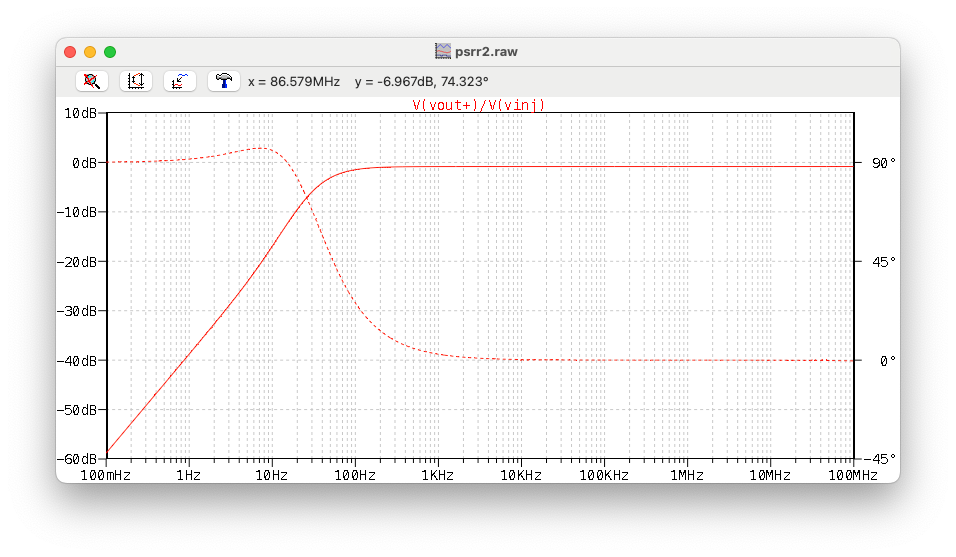 Frequency response of the PSRR Injection Board (from the injection SMA to the DUT).
There is a flat response above 100Hz, and a 20dB/dec rolloff below 100Hz — but for measuring down to 1Hz this is more than easily accounted for in your measurement system.
The PCB
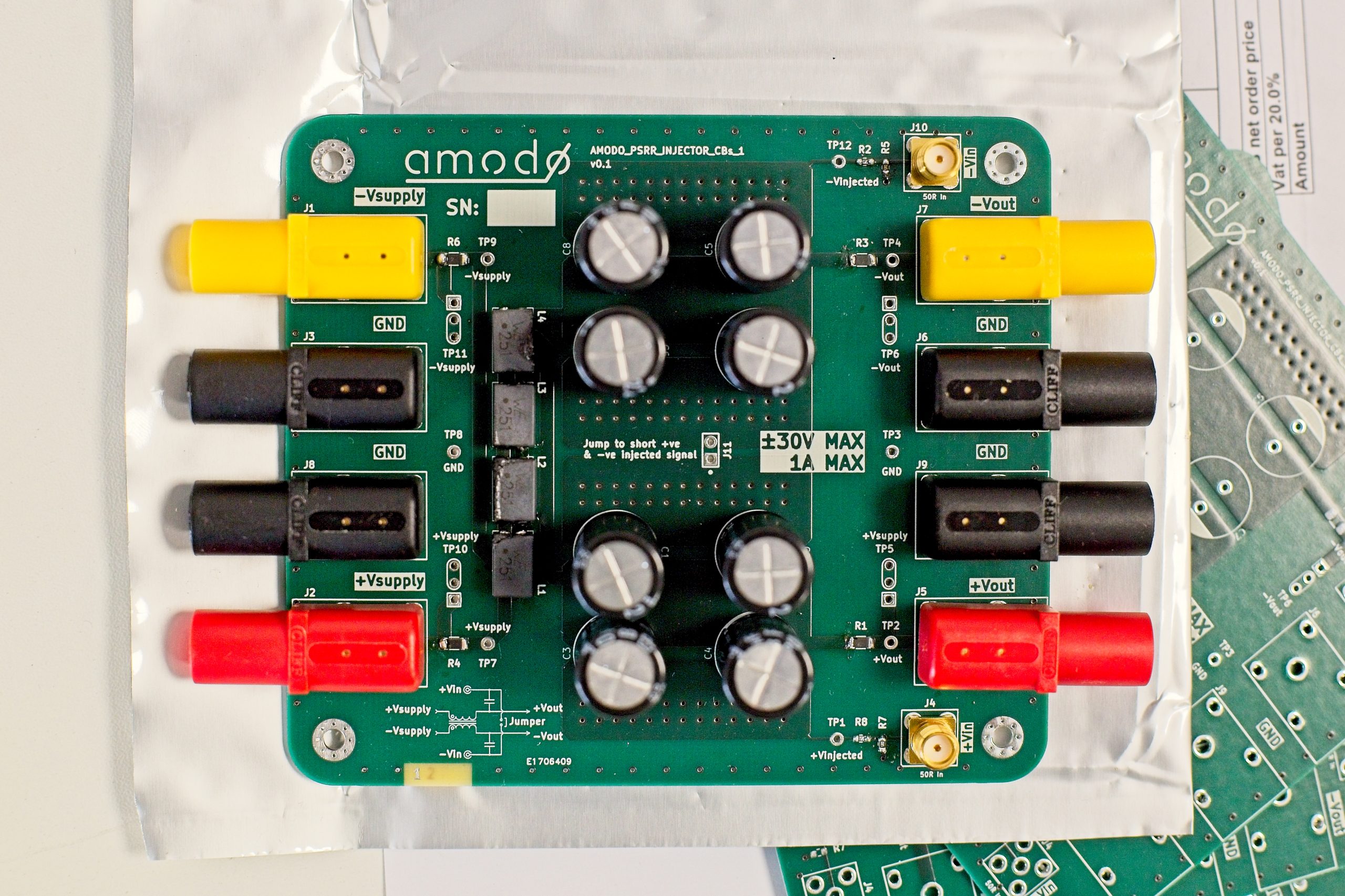
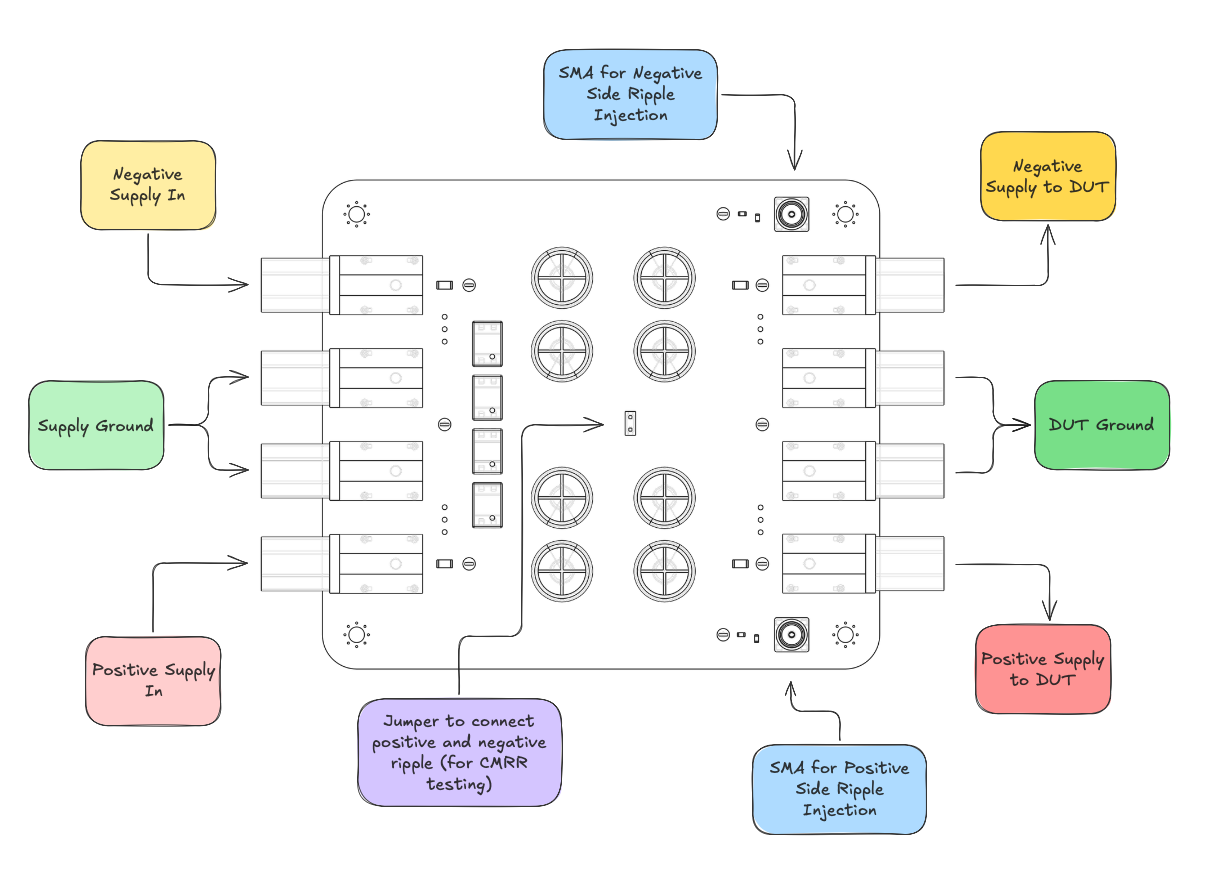 Labelled diagram of Amodo’s power supply ripple injector board.
We implemented the above circuit in a mirrored format to allow noise to be injected on either the positive or negative supply.
Connect your supply to the banana plugs on the left, your function generator to the SMAs and your device being tested to the banana plugs on the right.
 Power Supply Ripple Injector Board.
Make it yourself
This design contains no secret sauce, so if you need a simple system to measure PSRR, please grab the Gerbers and get a board made.
PCB design files and schematics available on GitHub.