
Test Equipment
EITSYS
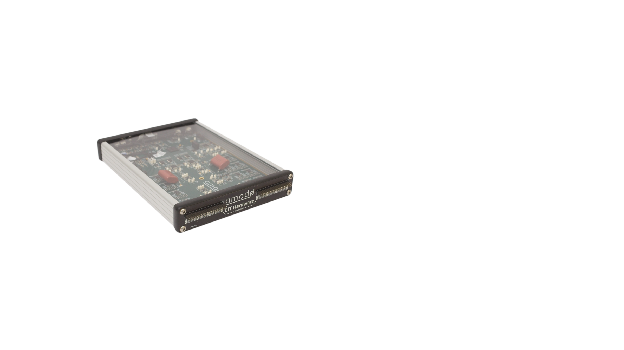
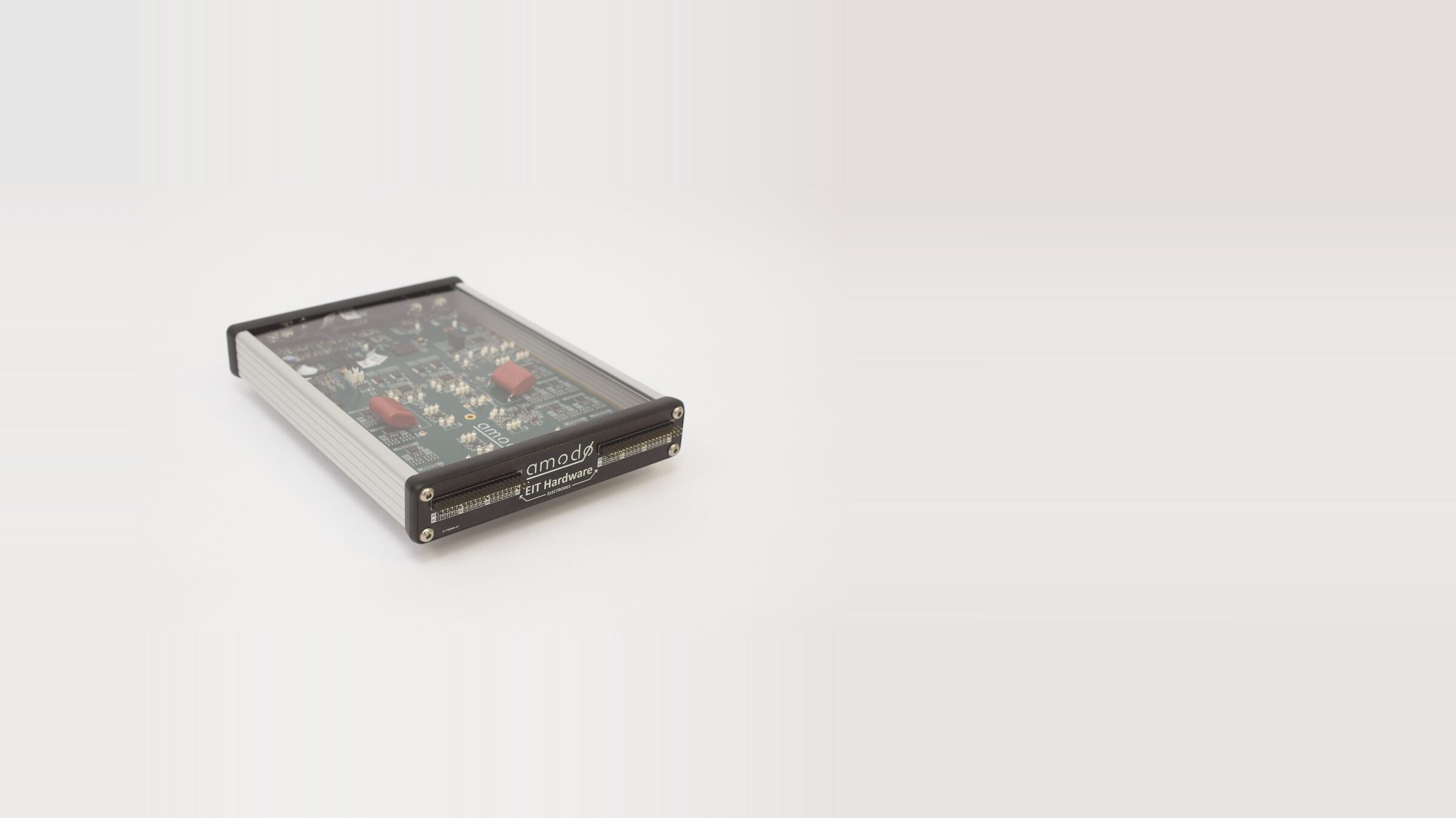
Benchtop EIT system
A configurable hardware platform for electrical impedance tomography. Drive AC currents across up to 64 electrodes, sweep frequencies from 1 kHz to 1 MHz, and reconstruct the impedance distribution inside soft bodies, robotic manipulators, and reaction vessels — without radiation or ionising fields.
A configurable hardware platform for electrical impedance tomography.
-
Electrodes
Up to 64
-
Excitation
1 kHz – 1 MHz
-
Frame rate
Up to 14,000 fps
-
Interface
USB serial CLI
Electrical impedance tomography is a non-ionising way of seeing inside an object. An array of electrodes around the object's surface produces an image of the impedance distribution within.
Our EITSYS hardware drives the electrodes, runs the scan, and streams the data to your computer for reconstruction.
It's built for researchers and engineers integrating EIT into experimental setups — soft robotic skin sensors, perfusion and ventilation studies, tank and column monitoring, and other situations where you need to see inside something opaque, in real time, without radiation.
How does it work?
Electrical Impedance Tomography is an imaging technique that uses an alternating output current in combination with voltage measurement to construct an image of the impedance distribution within a domain bounded by an electrode array. Typically, it is used for non-radiating medical imaging.
The Amodo EIT hardware computes a measurement using four terminals. An alternating stimulation current is injected across the transmit electrode pair, which develops a voltage across the load impedance being measured. The receiver then differentially measures the voltage developed across the load.
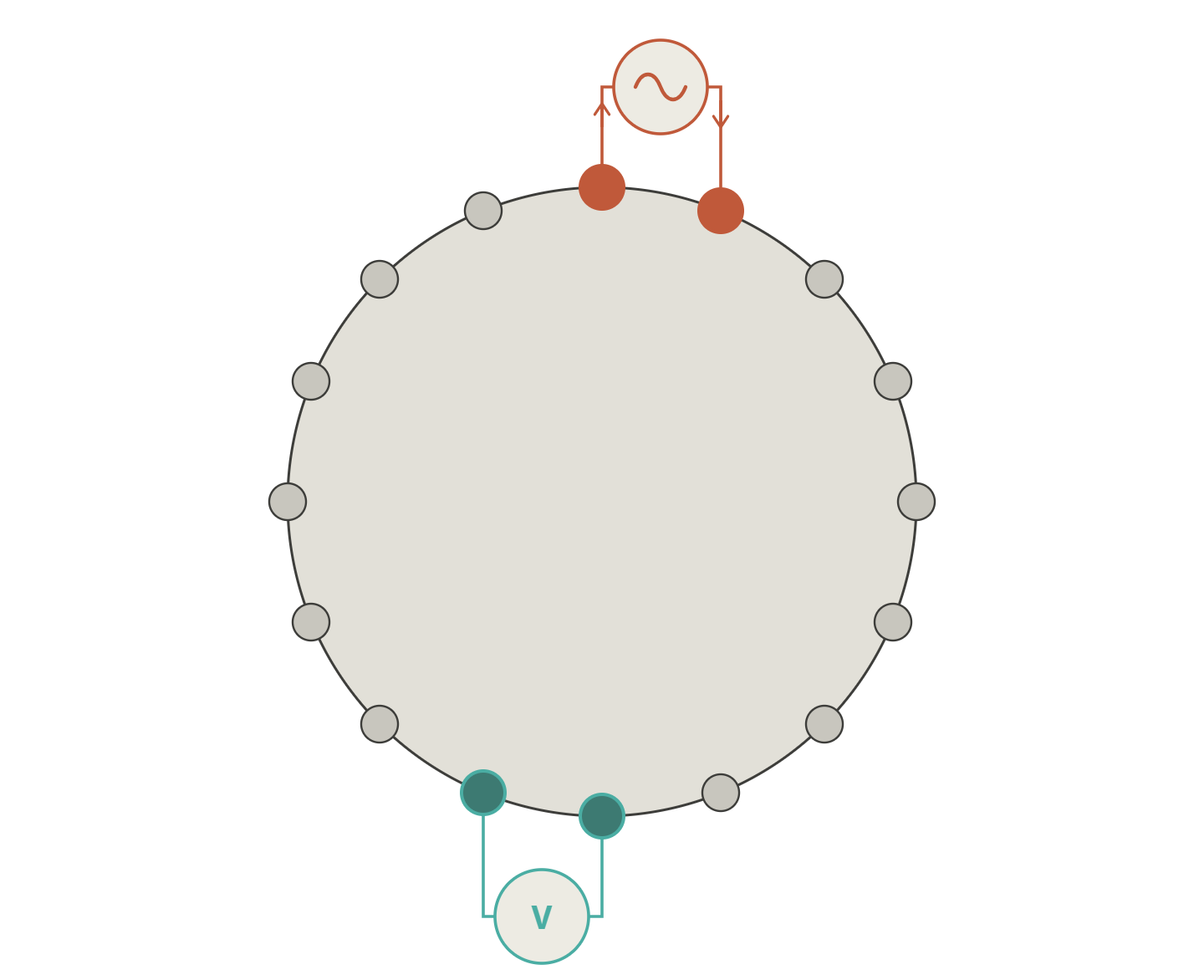
The Amodo EIT hardware has an output multiplexer that allows any of the four measurement nodes to be connected to any of the device output electrodes. A measurement combination is a set that describes where to connect the two transmit and two receive electrodes. A frame is made up of a number of measurement combinations.
Typically, an adjacent or opposite drive topology will be configured. For adjacent drive on a 16 electrode setup, electrodes 1 and 2 are configured as the stimulation electrodes, and then voltage measurements are taken between electrode pairs 3,4 through 15,16. This gives 13 measurements for stimulation pair 1,2 and 208 total measurements for all 16 possible stimulation pairs. The Amodo EIT interface allows users to pre-load a list of measurement combinations that make up a frame. A frame can be made up of up to 100,000 measurement combinations, in any configuration imaginable.
The transmit path has adjustable gain, allowing the device to adjust the stimulation current for maximum output voltage amplitude into a range of load impedances. The receive path has adjustable gain, and this is adjustable on a per-measurement basis. This means that the gain is adjusted continuously whilst scanning through the frame, increasing the signal-to-noise ratio for the case where the receive electrodes are loosely coupled to the transmit electrodes.
Device Overview
| Electrode array | |
|---|---|
| Electrodes | Support for up to 64 electrodes. |
| AC excitation | AC excitation current between any two electrodes. |
| Voltage measurement | Voltage measurement between any two electrode. |
| Simultaneous | Stimulation and measurement can be performed simultaneously on the same electrode pair. |
| Output stage | |
| Excitation current | Configurable between 1 kHz and 1 MHz, in 1 kHz increments. |
| Transmit gain | The transmit gain between the sinusoid synthesiser and voltage-to-current converter is programmable from 1/64 to ×32 in power-of-two steps. |
| Compliance voltage | ±14 V on the output current stage. |
| Input stage | |
| Receive gain | The receive gain between the input electrodes and ADC is programmable from 1/64 to ×256 in power-of-two steps. |
| Auto-gain algorithm | Comprehensive auto-gain algorithm which applies unique transmit and receive gain for each measurement combination to significantly improve SNR. |
| ADC | 12-bit ADC, up to 4 Msps; measurements sampled synchronously with the stimulation current. |
| Setup | |
| Frame preloading | Up to 100,000 measurement combinations comprising electrode connections and gains may be pre-loaded into device memory for back-to-back measurements resulting in a frame. |
| Frame rate | Up to 14,000 frames per second when a single measurement-combination frame is configured. |
| Typical configuration | Typical configuration for 60 Hz framerate: 16 electrodes (208 measurements per frame) at 50 kHz stimulation. |
| Configuration & data | USB serial CLI interface for configuration of the device and retrieval of measurements. |
| Operation | Headless operation. |
| Power draw | Provided with an AC/DC power supply (24 V output, 85–264 VAC input); 6 W typical power consumption. |
| Form factor | |
| Enclosure | Robust and portable extruded aluminium enclosure, 220 × 165 × 30 mm. |
| Output connectors | 0.1″ pitch 2×20 way output connectors. |
| Weight | 700 g - without power supply or cabling. |
Disclaimer
EITSYS is an electronic module designed for integration into robotic applications and experiments for research purposes. It is not intended to be used in medical devices.
Purchase one for your project
Buy EITSYS £3,850Prefer an invoice or purchase order, or have questions before you buy? Get in touch.

Need new hardware designing?
Talk to our engineering team about your requirements.