Scaling Recomputation Inference Verification
Moving our DiFR prototype to an asynchronous, ledger-based architecture on a Kubernetes cluster, and measuring the verifier's compute advantage.
Contents
This post details some architectural modifications we made to our Inference Recomputation Prototype. There were a few reasons for this (priority order):
- Passive TAPs: It’s on the critical path to verifying inference traffic captured by passive TAPs.
- Scaling issues & performance: We wanted to prototype a more scalable system to find issues at larger scale, and measure the relative performance requirements of verifier vs. prover.
- Implementation cleanup: The original prototype was relatively scrappy, as we mostly wanted to test DiFR on our hardware. We wanted to build a more robust and adaptable system to enable our future work.
This post includes some preliminary performance findings, and technical details of our implementation of the architecture.
Background
In our Stage 1 Inference Verification Prototype we implemented the DiFR algorithm (Karvonen et al.) using modified open-source software. We demonstrated that inference output in typical LLM chat applications could be reliably blocked using the results of recomputation verification with a few examples of dishonest prover models.
Motivation: Passive TAPs and asynchronous verification
In the architecture we introduced in Stage 1, the verifier performs verification as soon as an inference request completes. The inference response was blocked from passing to the user until the verification passed. We term this synchronous verification.
An alternative is performing verification some time after the inference request completes. We term this asynchronous verification.
Asynchronous verification is important: it’s how the system must work when passive network TAPs are used. The passive TAP cannot block the inference result while verification is running, as it is “passive”.
Asynchronous verification also provides some performance benefits:
- Verification jobs can be batched to increase cluster GPU activity, improving efficiency.
- Grouping related jobs (multi-turn chat) to improve KV cache hit rate.
- Grouping jobs related to the same model and sampling configuration.
- Grouping jobs based on required KV cache size.
- Verifier model instances are launched when required, rather than being kept on standby taking up a GPU.
Running recomputation verification at scale could present new challenges:
- Multiple models: The verifier system could be required to verify inference from multiple models, potentially with varying sampling configurations that affect the inputs to DiFR (described in Stage 1).
- Throughput fluctuation: The pattern of inference requests is not predictable. We can expect large fluctuations in verification demand.
Extra: Implementation cleanup
In addition, we wanted to clean up some of the scrappy implementation. In particular architectural separation. Previously, the verification system was built into Open WebUI. A chat system is a bad place to house verification logic!
An architecture for asynchronous verification
The new architecture revolves around a “ledger”, which acts as a buffer for recomputation events. The verifier can read items out of this buffer asynchronously from the original inference requests.
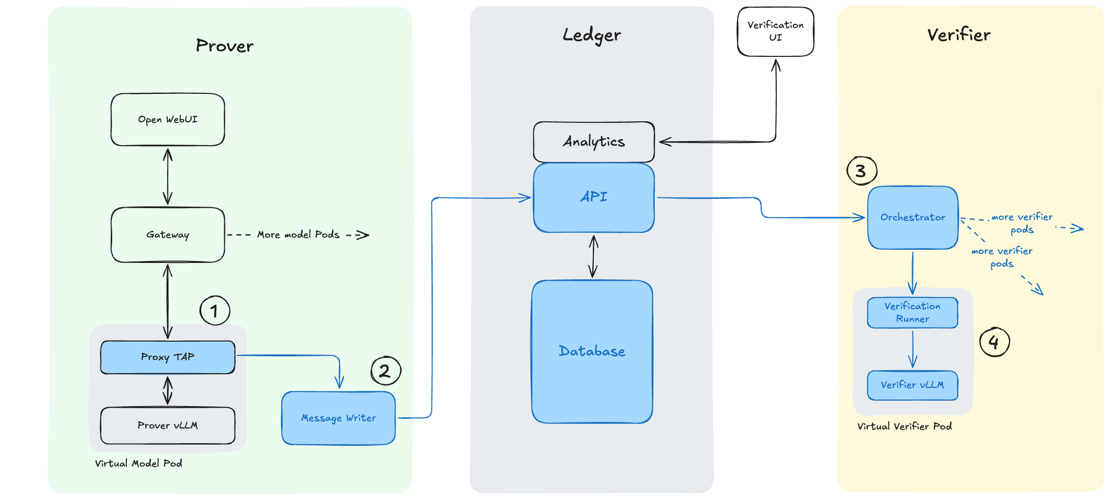
- The proxy TAP sits on the pod running the model as a “Sidecar” and captures the incoming events for a model as well as the model’s response. This input-output pair is then forwarded to the message writer. This part will be replaced by a physical TAP on a network link in the future.
- The message writer transforms the capture data and stores this into the ledger as “inference events”. The ledger acts as a store for all events, including both the inference events and the corresponding “verification events”.
- The orchestrator monitors the inference events in the ledger which sit there unverified, and spins up new verification runners for models which don’t have a verifier pod live.
- The verification runners are started with instructions to load a specific model. They perform inference verification for all inference events in the ledger that are not yet verified. If there are no inference events matching the model, the verification runner will shut down and unload the model to free space on the verifier system. The verification UI acts as a way to inspect the state of the ledger and view the results of inference verification.
Each of these components is covered in more detail in the appendix at the bottom of this post.
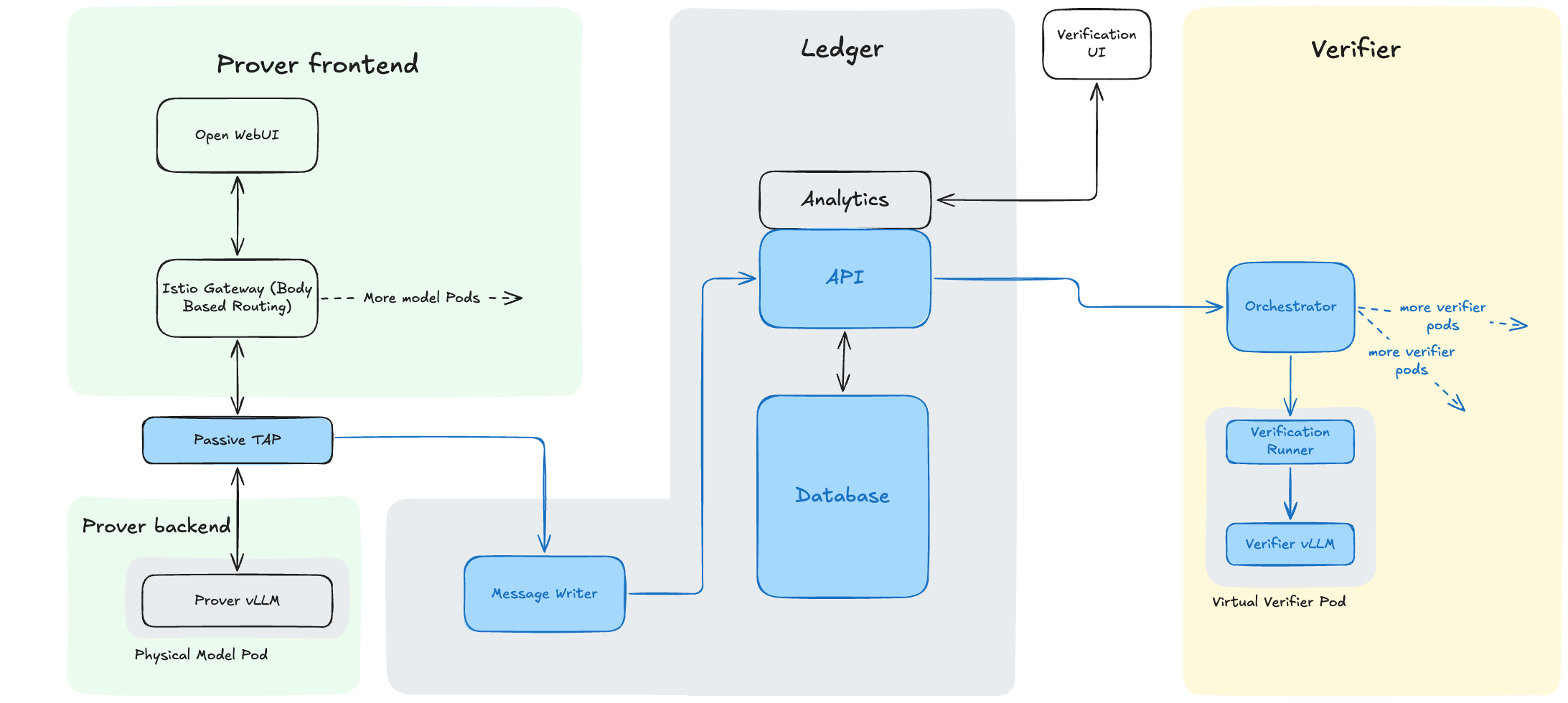
In the future, the software proxy TAP will be replaced by a physical passive TAP. This new ledger architecture allows this. A future architecture is shown in Figure 2.
Issues we found
Sampling Discrepancies
We had issues with verification during initial testing of the new architecture: valid prover inference events were failing verification with large logit difference values. This pointed towards discrepancies in the sampling algorithm between the prover and verifier.
Deeper investigation revealed that the Random Number Generator (RNG) implementations were different between the prover and verifier. This was caused by use of a newer version (v0.25.1) of vLLM for our prover model instances.
DiFR was originally implemented against v0.10.1 of vLLM that used the V1 model runner. Between v0.10.1 and v0.25.1 a new default V2 model runner was introduced with a different RNG implementation. The sampling implementation for our inference generated by vLLM v0.25.1 did not match that expected by DiFR, causing large logit differences to be calculated. The fix is to force vLLM to run on the V1 model runner so the sampling algorithm matches that expected by DiFR.
In the real system, a verifier and prover would have to ensure they are using the same sampling algorithm. This would likely be part of the “model commitment”, along with weights, etc.
Weights Caching
Initially, each vLLM instance was pulling the weights from the Hugging Face repository, leading to greater than 10 minute launch times. This was resolved by implementing a local cache on each node.
In the real system, we would expect weights to be pre-loaded into the verifier system as part of the “commitment” process.
Performance testing
One of the motivations for this experiment was to get an estimate of the computational overhead for inference recomputation using DiFR. This section explains some of the performance details, but we note that in most verification schemes we’d only expect to verify a sample of the traffic, reducing the computational overhead.
Monitoring GPU Performance
Monitoring GPU performance across a cluster is challenging. “GPU utilisation” is a misleading metric (link) and sample rates are low (< 5 Hz) (link). The available metrics depend on the GPU vendor and SKU.
Our current cluster only contains Nvidia GPUs. We use Nvidia DCGM Exporter and Prometheus to scrape metrics from all GPUs in the cluster at 5 Hz.
The calculation we perform depends on the number of concurrent jobs running on the GPU.
- When concurrency is 1, we take an integral of “pipe activity” over the execution time. Pipe activity reports the number of cycles the tensor cores are doing work, which gives us performance metrics for each individual inference event. Verification events are mapped to which GPU is running them to get pipe activity for the correct GPU.
- When concurrency is > 1, we cannot generate metrics for each individual event. There is no low-overhead way to assign pipe activity to different GPU jobs. To avoid double counting, we have to integrate pipe activity over an entire testing run (many inference events).
The ratio of integrated pipe activity between the verifier and prover gives the “verifier compute advantage” (VCA). We believe this is good enough to produce some rough bounds on the relative number of GPUs required for verification vs. original prover inference.
Response length
Longer inference outputs are beneficial in this case as we can collect more activity samples, giving a more precise pipe activity reading even at our low 5 Hz sampling rate. To this end, we have amended our prompt runner suite from Stage 1 to request longer outputs from the models (5000+ tokens).
Results
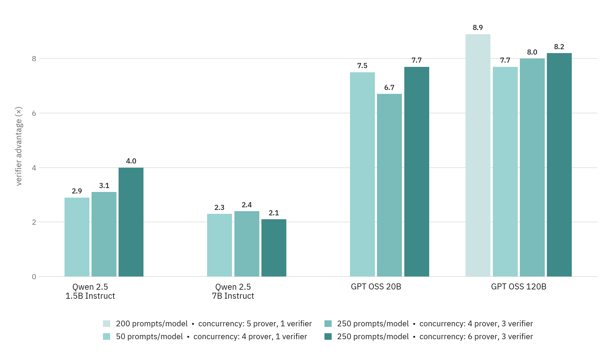
Our early results are shown in Figure 3 and indicate a 2–8 times performance advantage for the verifier.
We believe most of this advantage comes from increased parallelism of the prefill operation used in token-DiFR, which is less memory-bandwidth bound than decode. This allows improved parallelism. This is reflected in the way we see a greater performance advantage with the larger models where this is better utilised. The verifier advantage is therefore dictated by the ratio of the MFU between the prover and verifier.
Future work
As part of future work, we could:
- Investigate whether algorithms that optimise for KV cache hit rate on the verifier could improve the verifier compute advantage.
- Ascertain how verifier advantage changes with different prover workloads (Q&A style requests vs. long context).
However, we do not think that increasing certainty on performance to sub-OOM precision is load-bearing on the viability of recomputation schemes - there are more important cruxes!
Appendix: Implementation details
Orchestrator/cluster
We implemented a miniature cluster using Kubernetes as an orchestration platform. The hardware is outlined in Table 1.
| Server Name | Chassis | GPUs | Kubernetes Role |
|---|---|---|---|
| amodo-cray1 | HPE Cray XD670 | 8 × Nvidia H100 SXM | Controller and Worker |
| amodo-gigabyte-1 | Gigabyte G294-Z21 | 2 × Nvidia H200 NVL | Worker |
| amodo-gigabyte-2 | Gigabyte G294-Z21 | 2 × Nvidia H200 NVL | Worker |
Table 1: Prototype Kubernetes Cluster Hardware
We removed the controller taints from amodo-cray1 so that its GPUs could be used in our testing.
Prover Model Instances
We now serve multiple model instances using the open source Kubeflow KServe software. Each model instance is defined as an LLMInferenceService in the Kubernetes manifest. This resolves to a vLLM container.
An Istio gateway is used to serve the different models behind a single endpoint. The model name from each request is used to forward traffic to the correct model.
An instance of Open WebUI is hosted with the relevant connection for each hosted model pre-configured for basic testing.
Ledger
The ledger-api is a Python FastAPI and PostgreSQL instance designed to record inference events and their corresponding verification. This is the source of truth for the other components in the verification architecture. The ERD for the ledger database is shown in Figure 4.
Model configurations and deployments are also stored in the ledger so we can track the model instance that produced the inference. We store DiFR settings for the threshold and Δmax against each model, which need to be set empirically.

Proxy Tap (inf-proxy)
This component utilises nginx and a Python FastAPI to proxy the vLLM OpenAI API. Calls to chat completions endpoints are redirected to the FastAPI, allowing the required inputs for DiFR to be scraped from the traffic and reported to the ledger.
The proxy tap is launched as a sidecar container to the prover vLLM container. Collocation with the running model instance limits the possibility of the traffic being tampered with before collection. Information about the running model is reported to the ledger at launch.
Message Writer (message-writer)
The message writer acts as a translation layer between the proxy tap and the ledger. Primarily, this is implemented as a separate component to make integration of network TAPs simpler in future.
Verification Runner
The verification runner completes DiFR calculations on inference events to perform the verification, as in Stage 1. Each runner has a paired vLLM instance running the verification model.
After launching, the runner will pull all pending inference events from the ledger for its model and process them. The concurrency of request processing is controlled by an environment variable passed in when the runner container spawns.
Orchestrator (inf-ver-orchestrator)
The orchestrator acts as the decision maker for when verification events are processed. This implementation uses a basic loop that monitors for inference events in the ledger. When events appear, it spawns verification runners to process them. One runner is spawned per unique model configuration for the available events.
We intend to expand this decision making algorithm to optimise the utilisation of verifier GPU compute. This may include optimising for KV cache hit rate and verifying a sampled set of inference events.
Verification UI (inf-ver-ui)
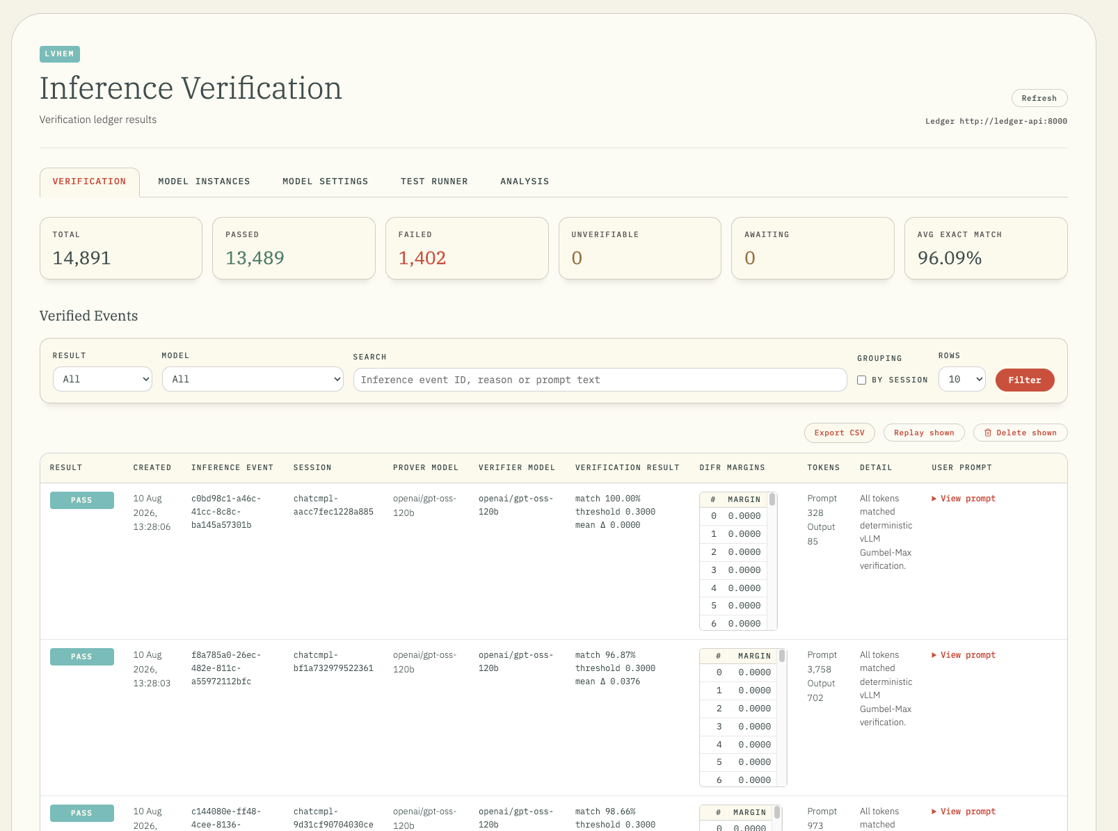
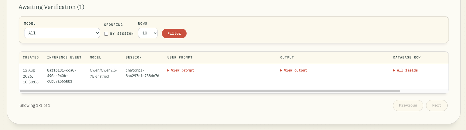
Figure 5 shows a refactor of the implementation in Stage 1 intended as an aide for testing. Different tables are shown for the pending and processed inference events. Separate tabs are also available for viewing model instances and configuring DiFR settings for each model.