Network taps, systems that split and copy network packets in a data centre, have recently been raised as a possible technology used as part of international AI verification plans. We’ve started to evaluate and prototype these systems.
Background
- Frontier AI risks may require international agreements and successful agreements require verification — checking everyone’s actually following the rules.
- A recent RAND working paper (Baker, Kulp, Marks, Brundage, Heim 2025) proposes six layers of verification for large-scale AI compute. One of those layers: off-chip network taps.
- The idea: large-scale AI training means thousands of chips talking over a data centre network. Tap that traffic, check it matches what the operator says they’re running.
- So it’s worth starting with basics: can you tap a data centre link, what do you get, and what breaks at production speeds?
At least in theory, implementing a network tap is as simple as buying an off-the-shelf optical tap and installing a system for capturing the data.
Network taps: passive vs. active
Network taps are either “active” or “passive”:
Active tap - a powered device that receives, copies, and retransmits traffic. The data goes from optical, to electrical for copying, then back to optical.
These systems require electronic components, and they interact with the network data. Whilst not impossible to secure, they do have a larger security attack surface and will be more difficult to verify.
Passive tap - passive splitters, these taps simply split the signal without actively interacting with the packets.
They have no active electronics to hack and nothing to configure. They’re likely to be more securable and more trustworthy. In this post, we’ll focus on these.
The usual way to achieve passive splitting is to splice the optical fibres in optical links, bifurcating the optical signals. These signals pass through a prism that sends the light on to two destinations. This isn’t a new technology; optical network taps are already used to debug networks, as a security system to detect intrusion, as a method for law enforcement to monitor a network, and more.
Signal modulation and power budget
A passive fibre tap splits the light without amplification, which means that the original destination will receive less optical power (a weaker signal). As the transmission distance increases, signal strength decreases, signal-to-noise ratio (SNR) increases. The faster the line, the more difficult it is to recover signals with low SNR. A larger fraction of the bits on the stream are unrecoverable from the noise - the bit error ratio (BER) increases.
Fibre taps come with different split ratios, e.g. 50:50 or 30:70. This ratio represents the fraction of the optical power which goes to each output destination.
How much this matters depends on the modulation:
-
At 10G — NRZ modulation (two-level on/off keying). The receiver just distinguishes two states, so it’s very tolerant of insertion loss. A typical 50/50 tap leaves plenty of margin.
-
At 400G — PAM4 modulation (four-level). The receiver needs a significantly higher signal-to-noise ratio. The same insertion loss that’s invisible at 10G requires careful optical power budgeting at 400G.
This will be important as data centres move to faster and faster networks (e.g. 800G). We’ve started further analysis on the feasibility of fibre taps on fast (>400G) networks.
Fibre types
Datacenter fibre comes in two types. The tap must match the fibre type in use.
-
Multimode — wider core (50μm), which makes it easier to couple light into, so the transceivers are cheaper. The tradeoff: the wider core allows light to take multiple paths, causing the signal to spread out over distance. Limited to ~2km range.
-
Single-mode — narrow core (9μm), only one light path, so the signal stays clean over much longer distances. Transceivers cost more.
Connectors and transceivers
- A transceiver (SFP/SFP+ at 10G, QSFP at 40G+) is the pluggable optoelectronic module in the NIC that performs electrical-to-optical conversion. Wavelength- and fibre-type-specific.
| Two LC connectors, one for each fibre on a 10G cable. | 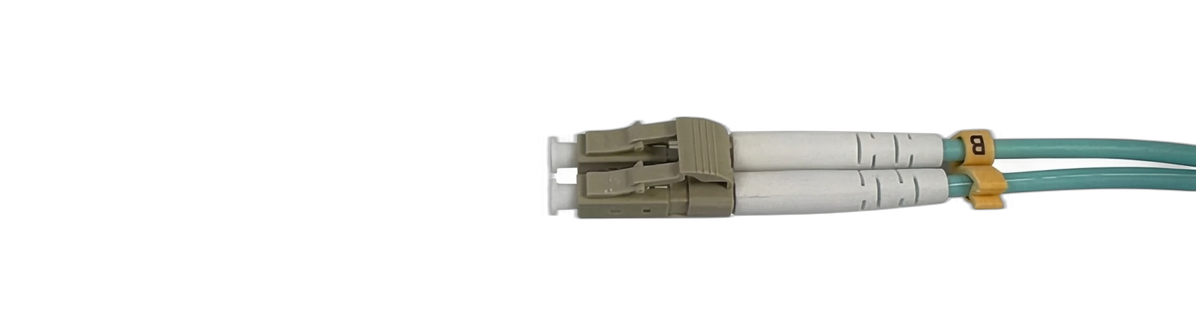 |
|---|---|
| A 10G transceiver without fibres plugged in. | |
| The 10G fibre with connectors plugged into the transceiver. | 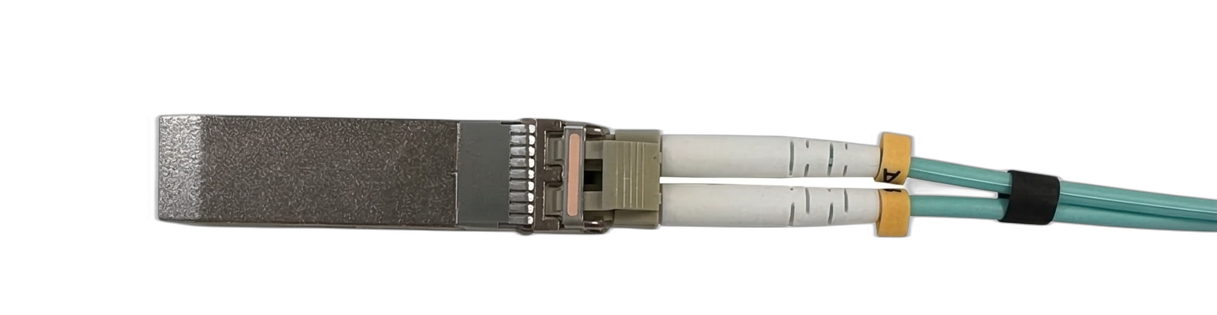 |
Faster connections use other transceiver/connector form factors. A common fast connector/fibre is a QSFP (Quad Small Form-factor Pluggable).
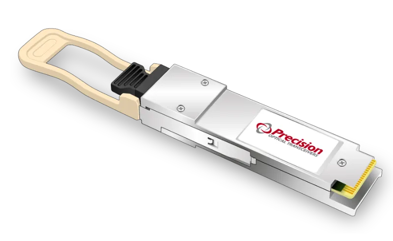 | 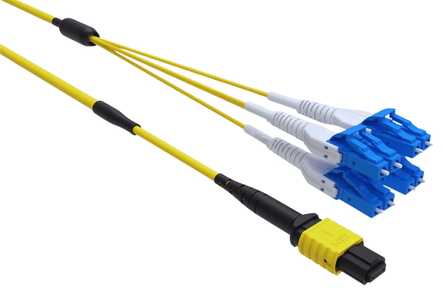 |
|---|---|
| QSFP transceiver. | A cable compatible with a multi fibre push on on one end and eight LC connectors on the other. |
Testing a slow network tap
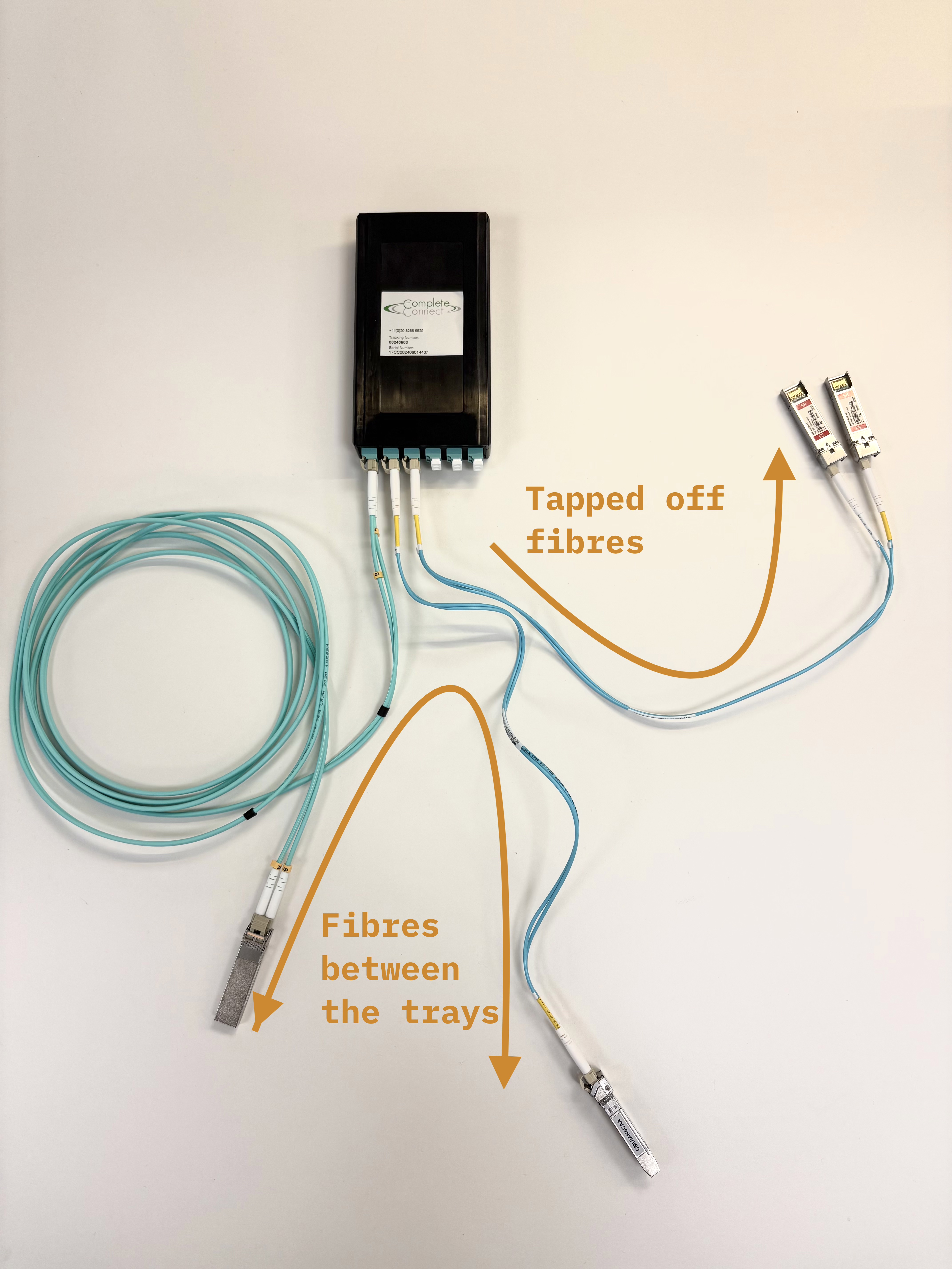
To get familiar with these setups, we installed a 10G, passive, optical network tap in our server.
We inserted a 2xLC multimode bidirectional passive splitter into the fibre link between a server NIC and the network switch. The splitter has monitor ports that output a copy of the optical signal — we connected a separate monitoring machine to these ports.
| Tap type | 2xLC multimode bidirectional passive splitter (OM4) |
|---|---|
| Throughput | ~10 Gbps each direction |
| Monitoring | Full packet capture on both directions of traffic |
| Cost | £250 for the tap cassette, £15 for fibres, and £50 for transceivers |
| Latency added | None — purely passive optical |
Steps to build this
The actual tap is simple, you plug fibres in and light gets split. The only things that took more than a couple of minutes’ work were:
-
Getting the DPUs into NIC mode. We used NVIDIA BlueField-2 DPUs as our NICs. For this project, we just needed them in NIC mode rather than DPU mode. Switching from the default required running mlxconfig with specific flags on the correct PCI device, then two full power cycles — not rshim resets, actual cold boots. This took most of a day.
-
This isn’t a relevant concern when installing network taps in real clusters.
-
Sourcing the tap. Common datacenter equipment suppliers sell tap cassettes but with ~2-month lead times. We found a smaller UK-based fibre optics company who make both multimode and single-mode tap cassettes and shipped fast.
We tested the setup by sending network traffic through the tap and confirming that both directions of traffic were being copied to the monitoring machine.
Going faster
Production AI training clusters use 400G or 800G Ethernet links (with 1.6T coming soon). The physics of passive splitting don’t change at higher speeds, but two things get harder:
-
Different optical standards. 400G uses different optical setups to achieve the much higher data rates. Commonly, we have more fibres. In 400G-DR4 (a particular optical standard), the link has 4 parallel lanes at 100G each, bundling 8 fibres into a single MPO-12 connector. A 400G tap needs to split all 8 fibres instead of just 2 — same principle, fewer off-the-shelf options. Other standards use bidirectional transmission over fewer fibres by multiplexing multiple wavelengths onto a single fibre, which would change the tapping approach.
-
Tighter power margins. PAM4 modulation at 400G is more sensitive to insertion loss. Whether an existing link has sufficient power budget for a tap depends on the specific transceivers and fibre runs in place — in the worst case, transceivers may need to be replaced, though this is manageable rather than a fundamental barrier.
We are quite confident that a 400G bidirectional passive taps are feasible; the relevant components exist, and the physics is well-understood. In theory, an 800G tap could be built, but it would have more signal-to-noise challenges than 400G.
This project came about because groups working on technical AI Verification policy wanted to understand what was physically possible in networking monitoring. We’re set up to quickly test your AI verification questions.
If you’re working on AI governance and have open questions about what the hardware can and can’t do, please reach out — we want to make sure we’re working on the most impactful problems.